

How To Install Electrical In Concrete Walls
How to Install Surface-Mounted Wiring and Conduit
With metal conduit, you lot can run power almost anywhere. We'll show you how to do it safely and easily.
Learn virtually the tools, materials and techniques yous need to cut, bend and install surface-mounted metal conduit. Add ability to a basement or garage shop with easy, cheap EMT (electrical metallic tubing).
You might too like: TBD
- Time
- Complexity
- Cost
- Multiple Days
- Intermediate
- Varies
Step 1: Program your run
For prophylactic, exposed electrical wiring (in the garage, basement and outdoors) must be protected by sturdy tubing. We chose 1/two-in. EMT metallic conduit for this projection considering information technology's easy to bend and gather (and have apart if you lot make a fault!). PVC conduit is another good option, but information technology differs in that yous glue the joints.
The kickoff step is to find your ability source. We tapped in to a xv-amp garage outlet receptacle to power the "light-duty" workbench area. If you copy this project and operate power-hungry tools such as circular or tabular array saws, you will demand to tap in to or run a new xx-amp circuit (see "Power-Hungry Tools"). Check the excursion billow in the main electrical panel to make up one's mind the circuit size. If you're uncertain about circuit sizing, consult a licensed electrician.
Adjacent, sketch the electric conduit route from your power source to the new electrical box locations and note the length of the run and all the boxes, connectors and wire yous need. Our materials included 1/2-in. EMT conduit (x ft. long), 4 10 iv ten one-i/2 in. metal boxes (which hold two receptacles; Photo 2), 4-in. square raised covers, ane one/2-in. showtime setscrew connector for each conduit/box connexion (Photo 2), plus one/two-in. couplings (to join ii pieces of conduit in longer runs), electric conduit straps, a 15-amp switch, receptacles and 14-gauge THHN wiring (the type of wire to run within the conduit). If y'all become ability from a 20-amp circuit, utilise only 12-estimate THHN wire. These items are at habitation centers and full-service hardware stores.
Cheque with your local edifice department to get a permit and an inspection for all work you lot practise.
Figure A: Electric Conduit Layout
This is a simple surface-mounted wiring plan.
Step 2: Bending basics
A 1/2-in. electrical conduit bender (Photo 5) is the but specialty tool you need to bend x-ft. sections of 1/2-in. EMT conduit. You'll also need a 3/4 x 24-in. water pipage, which serves equally the handle and screws into the bender head (Photo 5). Along with that, y'all demand basic mitt tools, a hacksaw and a drill with a 1/four-in. masonry bit. And you lot may need a fish tape to pull wire if you have long electric conduit runs with multiple bends.
We'll simply evidence how to brand ninety-degree bends, since they're the easiest and nearly often used. Another common bend is an outset, which is a difficult ii-office curve that positions the electrical conduit slightly off the wall to connect straight into electric boxes. We chose to employ showtime setscrew connectors (Photo 2) to simplify this task.
Bending electric conduit isn't difficult (Photo 7). Just you may not get perfect bends on the first try, and so buy an actress 10-ft. length only in example. If you lot don't desire to bend conduit, you tin purchase gradual "90-degree sweep bends" or "90-degree square corner elbow fittings." However, your projection won't look as professional considering of the numerous connectors, and the extra joints brand it harder to push or pull wire.
Step 3: Get-go at the power source
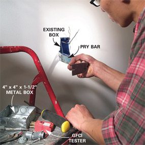
Photograph 1: Remove the quondam outlet
Turn off the power and remove the old receptacle. Pry the top and bottom box nails away from the stud to remove the box. Pull the wires through the wall opening.
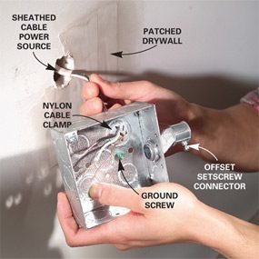
Photo 2: Add connectors to the box
Remove ane/2-in. knockouts and insert a 3/8-in. cable clench and an offset setscrew connector. Push the sheathed cable through the clench and into the box.

Photo three: Mount the box
Mount the box to the wall by driving ii one-5/8 in. drywall screws through the drywall and into the stud. Go on the box level.

Photo 4: Marker the conduit for cutting
Mensurate from the wall corner to a bespeak 3/iv in. within of the offset connector. Subtract 5 in. for the 90-degree bend, then mark that length on the electric conduit.
Afterward you've chosen the electrical box to tie in to, plough off the circuit breaker or unscrew the fuse that protects the circuit. Some electrical boxes may contain wires from more ane circuit. Before doing any work, examination all the wires with a non-contact voltage tester (sold at hardware stores and domicile centers) to brand certain they're "expressionless."
Side by side, remove the existing receptacle and box from the stud (Photo one). Now position (not attach) a 4 x 4 x one-one/2 in. metal electrical box on the drywall surface, slightly higher up or below the existing opening and then you lot can pull at least 1/4 in. of the cable sheathing through the back of the box (Photo three). Cutting the drywall and shift the box if necessary to get more sheathed cable inside the box. You take to patch the drywall anyway, before you screw the new box to the wall (Photograph three).
Step 4: Bending conduit
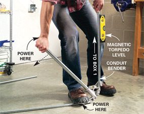
Photograph 5: Start the bend
Place the electric conduit in the bender with the mark directly in line with the pointer (run across adjacent photo). Step on the conduit bender and push button down on the handle until the conduit forms a xc-degree angle and is level.

Detail
Stop bending when the bubble reads level.
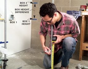
Photo half dozen: Marking the next cut
Measure the difference in height between Box 1 and Box 2 (in a higher place the bench; Figure A). Subtract 5 in. from the measurement, so add 3/four in. to allow for the thickness of the electric conduit. Mark that distance on the electrical conduit.
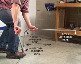
Photograph vii: Change the direction of the bend
Repeat Stride five to make the second 90-degree bend. Make sure yous bend it 90 degrees in the correct direction.
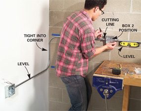
Photograph 8: Level and marking the electric conduit
Attach electric conduit loosely to Box 1. Level the horizontal sections, so position Box ii and marker the location of the cutting.
For 90-degree bends in 1/2-in. electrical conduit, the dominion is to subtract 5 in. from the connector-to-wall measurement. If the total distance is 33 in., marking the conduit at 28 in. Be sure to measure to the inside of the offset connector where the conduit actually seats (Photos 2 and four).
Bend conduit by positioning it in the bender so your distance mark on the conduit lines upwards with the bender pointer (Photo 5 and inset). Apply pressure with your foot and hand to curve the end of the conduit straight upwards. So check the bending with a magnetic torpedo level (or with the chimera level built into some bender heads) and adjust the curve until y'all get 90 degrees.
When measuring for the vertical rise, mensurate the height deviation between the 2 boxes. Again, have that distance and decrease 5 in. And so add 3/4 in. to account for the thickness of the conduit in the start bend (Photo 6).
Ability-hungry tools
If you program to power whatsoever tools, be aware that a common xv-amp circuit may overload and trip if any of the following tools are run simultaneously (especially if your store lights are on too):
Miter saw – 13 to 15 amps
Circular saw – 13 to fifteen amps
Router – 9 to 11 amps
Belt sander – vi to 12 amps
We recommend a maximum connected load (lights and other permanently plugged in devices) and operating load (tools and other temporarily running devices) of 1,440 watts (12 amps) for a 15-amp circuit and 1,920 watts (sixteen amps) for a 20-amp circuit.
Step 5: Attach boxes to masonry

Photograph 9: Cut the electrical conduit
Cut the electrical conduit with a hacksaw. Scrape any sharp burrs from both the inside and the outside edges with pliers.
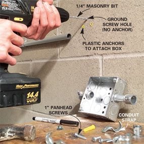
Photo ten: Drill the holes
Reposition the electric conduit and Box 2 and mark hole locations for plastic anchors. Drill the holes, then mount the box and conduit straps with panhead screws.
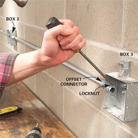
Photo xi: Tighten the locknuts
Position Box iii, measure the distance to Box 2 and cut the conduit to fit. Repeat steps 9 and 10 to mount them. Now tighten all offset connector locknuts with a hammer and screwdriver.
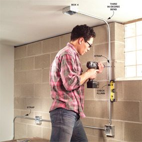
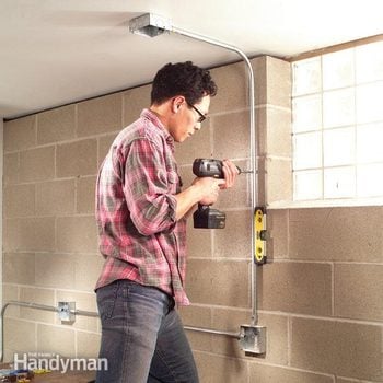
Photograph 12: Fasten long runs with straps
Measure from the Box iii kickoff connector to the ceiling, then repeat Steps 4 and 5. Plumb the conduit and attach a strap. Install Box 4.
Afterwards leveling the conduit and marking the location for Box two (Photo 8), be sure to smooth all cut edges with a pliers (Photograph nine). Now drill the two holes for plastic anchors and a clearance hole for the basis screw. Attach the box to the concrete with plastic anchors and panhead screws (Photo 10).
Echo this process to attach all other boxes, likewise every bit the straps that concur the conduit to the masonry. When using 1/2-in. EMT conduit, position straps within 3 ft. of each box and within 10 ft. thereafter. Once y'all've installed the conduit and rotated the offsets so the conduit rests against the wall, tighten the offset connector locknuts with a sharp rap of a hammer on a screwdriver (Photo 11).
CAUTION!
If y'all have aluminum wiring, leave it lone. Call in a licensed pro who's certified to work with it. This wiring is deadening greyness, not the dull orange that's feature of copper.
Footstep 6: Running the wire
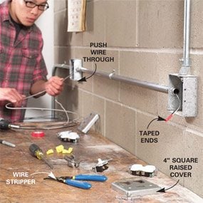
Photograph 13: Push the wire through short runs
Tape together ends of one blackness and one white 14-judge wire and button the taped ends through the conduit. Cut the wires, leaving 8 in. extra at each box. Echo this step from Box iii to Box 4.
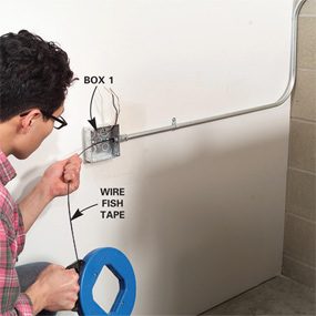
Photo 14: Pull wires with fish tape
Push fish tape from Box one to Box 2. Bend both wires through the fish tape claw and tape them, leaving the middle open to flex effectually corners, so pull wires back from Box 2 to Box 1.
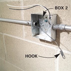
Detail
Push the fish tape to the 2nd box.
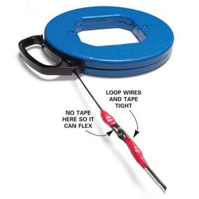
Fish Tape Particular
Record wire to fish tape.
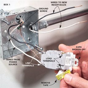
Photo 15: Wire the GFCI outlet
Connect Box i by first breaking the ears off a GFCI receptacle, then connect the wires from the ability source to the 'line' terminals, the wires to the new receptacles to the 'load' terminals, and the footing wire to the footing spiral. Then connect the devices in Boxes 2, 3 and 4 (see Figures B, C and D).

Detail
GFCI ears.
When running wire brusque distances with few bends, such as between Boxes two and 3, and 3 and four, yous tin simply tape the two wire ends together and push them through the conduit (Photo thirteen). For longer distances, or runs that accept two or more bends, run a fish tape through the conduit and tape the wires to it (Photo fourteen and DETAIL photo).
Garage receptacles must exist GFCI protected. Before wiring the GFCI receptacle into Box i, bend or pause off the top and lesser ears. Repeat this pace with all receptacles so they fit inside the metal box every bit well as screw to the 4-in. foursquare cover (that is raised 1/2 in.). Now connect the GFCI receptacle as shown (Photo 15), followed by the other boxes (Figures B, C and D). Then spiral all receptacles to the covers and attach the covers to the boxes.
Figures B – D: Wiring Connections
Wiring Connections in electrical boxes.
Additional Information
- Figure B: Box 2 wiring connections
- Figure C: Box 3 wiring connections
- Figure D: Box iv wiring connections
Required Tools for this Projection
Have the necessary tools for this DIY projection lined up earlier you commencement—you'll save time and frustration.
one/two″ conduit bender, fish tape
Required Materials for this Project
Avoid last-minute shopping trips by having all your materials ready alee of time. Here's a list.

Source: https://www.familyhandyman.com/project/how-to-install-surface-mounted-wiring-and-conduit/
Posted by: eppspong1938.blogspot.com
0 Response to "How To Install Electrical In Concrete Walls"
Post a Comment